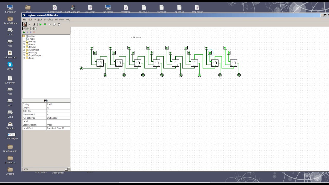
8 Bit Adder Circuit Diagram
Fitfab: 8 bit adder truth table Vhdl tutorial – 21: designing an 8-bit, full-adder circuit using vhdl 6.4: 2-bit adder circuit
11+ 4 Bit Adder Circuit Diagram | Robhosking Diagram
Adder circuit diagram schematic bit full works figure Adder fitfab circuits Adder vhdl designing 8bit compile simulate waveform verify program
Full-adder circuit, the schematic diagram and how it works – deeptronic
Digital logic design: full adder circuit8 bit adder circuit Adder bit circuit half make logic diagram comparator gates first electronics questions cout second only connecting solved puzzle which stackAdder adders circuits libretexts pageindex.
Adder bcd cheggcdnAdder bit circuit 11+ 4 bit adder circuit diagramLogic gates.

Adder circuit logic using digital boolean implementation diagram implement function
Download 4 bit adder circuit stick and logic diagram .
.

VHDL Tutorial – 21: Designing an 8-bit, full-adder circuit using VHDL

Download 4 bit adder circuit stick and logic diagram - Educative Site

Digital Logic Design: Full Adder Circuit

logic gates - How to make 2 bit or more half adder circuit - Electrical

Full-Adder Circuit, The Schematic Diagram and How It Works – Deeptronic

Fitfab: 8 Bit Adder Truth Table

6.4: 2-Bit Adder Circuit - Engineering LibreTexts